
The Abilis CPX frontal panel lodges a LCD display, a floppy disk drive, a power switch, two push buttons and three leds.
The LCD Display and the indicators give information about the Abilis CPX working mode, while the push buttons provide some utility functions described.
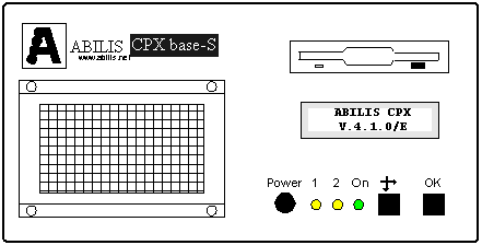
Figure 1. Front panel.
 Power - (Power switch)
If pressing the Power switch the green led does not light on, control that the power cable is
working and connecting the Abilis CPX to the current tap. The user should also check whether the tap
supplies the required voltage (220V). If, after executing all the previous verifications, the Abilis
CPX didn't switch on, please contact the assistance.
 On - (Green LED: Power indicator)
The green led starts to light on, immediately after Abilis CPX has been started through
switch Power. If, after pressing the Power switch, the green
led does not light on, control that the power cable is working and connecting the
Abilis CPX to the current tap. The user should also check whether the tap supplies
the required voltage (220V). If, after executing all the previous verifications, the
Abilis CPX didn't switch on, please contact the assistance.
 1 - (Yellow LED 1. It indicates the Abilis CPX works)
The yellow LED 1 lightens every second, when the Abilis CPX starts to working, after loading the software. The
yellow LED 1 flashes with higher frequency while the software is loading; it can slow down during disk access operation.
If both yellow LED 1 and yellow LED 2 do not flash simultaneously, it means that Abilis CPX is
blocked and it is necessary to switch off and then restart it.
 2 - (Yellow LED 2. It indicates the Abilis CPX works)
The yellow Led 2 lightens every (c.a) second, when the Abilis CPX starts working, after loading the software.
The yellow Led 2 do not flash (always lightened or off), while the software is loading; it can slow down during disk
access operation. If both yellow LED 1 and yellow LED 2 do not flash simultaneously, it means that Abilis CPX is blocked
and is necessary to switch off and then restart it.
 Select - (Confirmation for menu selection)
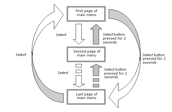
Every time the button Select, is pressed, the display will show the next menu. By pressing it a lot of times, all
the menus will be shown in a cyclic way.
Refer to section Using the display and function keys (Select and OK),
for a more detailed description.
 OK - (Confirmation key)
Pressing key OK it is possible to access information about the menu currently showed
on the LCD display. Moreover for those menus, that requires a confirmation, by
holding pressed the OK keys for an extended time, an affirmative answer will be given to the
request showed on the LCD display.
Refer to section Using the display and function keys (Select and OK),
for a more detailed description.
 Liquid Crystals Display.
The LCD is able to visualize two lines of sixteen alphanumeric characters. In order to allow an easy read
is necessary that the environment is sufficiently illuminated. If the display is not clearly legible, it is necessary to
change the observation angle, moving in horizontal and/or vertical sense.
 Floppy disk drive.
For a correct Abilis CPX working mode it is mandatory that the disk, containing the Abilis CPX software, is inserted.
The inserted disk must be NOT WRITE PROTECTED, contrary Abilis CPX will start regularly, but it won't be possible to
save either new configuration or log files.
The floppy disk is not write protected if the write enable "window" is closed. The floppy disk is write protected
if it is opened. The disk, containing the Abilis CPX software, must always be inserted, in the floppy disks drive, with the WRITE
PROTECTION disabled.
At the Abilis CPX start, the display visualizes the Messages Menu which shows on the first row the product name, on the second the software version currently in use.
The use of Select and OK push buttons is the following:
The picture shows how to scroll the menus.
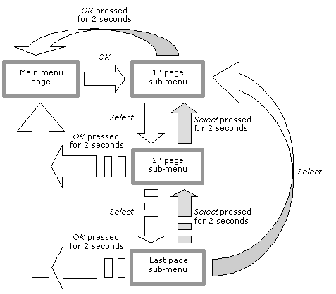
Pressing the OK key it is possible to access sub-menus.
The picture shows how to enter and leave a sub-menu, as well as the use of Select button to scroll within the sub-menu.
Messages Menu - Abilis CPX version and system messages.
The first row of the Messages Menu visualizes the system name, while the second shows informative messages about the system working mode. For example, after resources activation, during which it is visualized the software version, the message "START SYSTEM" will be shown to signal that Abilis CPX from that moment is regularly working:

The informative messages are displayed if, on the display, the Messages Menu is active. If one of the following menus is active, only eventual messages of errors or alarms will be displayed.Every time an informative message or an alarm is shown, pressing the OK key is possible to visualize again name and version of the product.
 State Menu of the link level ports
This menu allows displaying the status of the link level ports. Pressing the OK key, it is possible to access the first page of the menu, pressing successively the Select key all the other eventual pages will be shown in a cyclic way. Only the active and correctly "RUNNING" ports are shown. Each page shows information about two ports:

Where:
If no Link ports are running, the following message will be shown:

Press the OK for at least 2 seconds to go back to the main Menu.
Maintaining the display on a page, every second the state of the port(s) shown on that page is refreshed.
 State Menu of the protocol ports
This menu allows displaying the status of the protocol ports. Pressing the OK key, it is possible to access the first page of the menu, pressing successively the Select key all the other eventual pages will be shown in a cyclic way. Only the active and correctly "RUNNING" ports are shown. Each page shows information about two ports:
Where:
If no protocol ports are running, the following message will be shown:

Press the OK for at least 2 seconds to go back to the main Menu.
Maintaining the display on a page, every second the state of the port(s) shown on that page is refreshed.
 State Menu of the VOICE ports
This menu allows displaying the status of the VOICE ports. Pressing the OK key, it is possible to access the first page of the menu, pressing successively the Select key all the other eventual pages will be shown in a cyclic way. Only the active and correctly "RUNNING" ports are shown. Each page shows information about twenty ports:

Where:
If no VOICE ports are running, the following message will be shown:

Press the OK for at least 2 seconds to go back to the main Menu.
Maintaining the display on a page, every second the state of the port(s) shown on that page is refreshed.
 State Menu of the ISDN PRIMARY channels
This menu allows displaying the state of ports and ISDN primary rate channels. Pressing the OK key, it is possible to access the first page of the menu, pressing successively the Select key all the other eventual pages will be shown in a cyclic way. Only the active and correctly "RUNNING" ports are shown. Each ISDN PRI port requires two pages, in the first one Level 1, Level 2 states and "Slips" are shown, in the second is shown each B channel state.
First page:

Where:
Pressing the Select key, the second page will be shown:

Where:
Pressing the Select key the next port will be shown.
If no ISDN-PRI (EPQ931) ports are running, the following message will be shown:

Press the OK for at least 2 seconds to go back to the main Menu.
Maintaining the display on a page, every second the state of the port(s) shown on that page is refreshed.
 State Menu of the ISDN BASIC RATE channels.
This menu allows displaying the state of ISDN Basic Rate channels. Pressing the OK key, it is possible to access the first page of the menu, pressing successively the Select key all the other eventual pages will be shown in a cyclic way. Only the active and correctly "RUNNING" ports are shown. Each page shows information about 4 pair of channels:

Where:
If no ISDN-BRI (Q931/EBQ931) ports are running, the following message will be shown:

Press the OK for at least 2 seconds to go back to the main Menu.
Maintaining the display on a page, every second the state of the port(s) shown on that page is refreshed.
 Menu of compression statistics
This menu allows displaying the compression statistics of the protocol ports. Pressing the OK key, it is possible to access the first page of the menu, pressing successively the Select key all the other eventual pages will be shown in a cyclic way. Only the active and correctly "RUNNING" ports are shown. Each page shows information about two ports:

Where:
If no protocol ports type is running, the following message will be shown:
Press the OK for at least 2 seconds to go back to the main Menu.
Maintaining the display on a page, every second the state of the port(s) shown on that page is refreshed.
 Menu of System utilities
This menu can execute operations related to system management, such as enabling/disabling the acoustic signal, system restart or saving the Events Log (Debug Log), or the current configuration. Pressing OK key the user accesses the first page of the menu, pressing the Select key all the other pages are visualized in a cyclic way.
Enabling/disabling the acoustic alarm signal:
The purpose of this utility command is the same of the SOUND DISABLE and SOUND ENABLE commands that are available through the Control Port command-line interface.
If the signal is already enabled, the following message will be shown:

If the signal is already disabled, the following message will be shown:

The purpose of this utility command is the same of the RESTART SYSTEM command that is available through the Control Port command-line interface.
The following message will be displayed:

Saving the Events Log (Debug Log):
The purpose of this utility command is the same of the SAVE DEBUG command that is available through the Control Port command-line interface.
The following message is displayed:

Saving the current configuration:
The purpose of this utility command is the same of the SAVE CONF command that is available through the Control Port command-line interface.
The following message is displayed:

Creating a backup copy of the current configuration:
The purpose of this utility command is the same of the SAVE CONF BACKUP command that is available through the Control Port command-line interface.
The following message is displayed:

 Menu of alarms displaying
The purpose of this menu is the same of the ALARM VIEW command available through the Control Port command-line interface.
It displays a list of those ports where an alarm event occurred. Being the alarm condition checked every 30 seconds, it is possible that 30 seconds could pass from the moment the port starts to correctly work again and to the one when the alarm event ends.

Where:
If there are no ports in alarm condition, the following message will be shown:

Maintaining the display on a page, every second the state of the port(s) shown on that page is refreshed.
Do not forget that this menu shows only those ports, whose parameter "LOG:" is set to "A", i.e. the periodic alarm event condition detection is requested.
 Menu of alarms management
This menu allows working on those ports, which are in an alarm condition not recoverable automatically but only manually. The most frequent cases are the SDLC, HDLCT and MLM/Slink ports in their STOPPED state: because of the error type they have to be manually reset.
In such cases, if the ports parameter "LOG:" is set to "A", those ports will be contained in the "alarm list" and they can be reset from the Menu of alarms management.
The result is the same as the ALARM RESET command is executed through the control port and the command INIT PO: is sent to all the alarmed ports.